
안녕하세요 여러분 민(Min) 입니다, 최근 제가 Python을 활용한 연구를 공부하던 중 가장 기본이 되는 3Bus System에 대한 분석자료를 아래와 같이 공유드립니다.
계통 구성
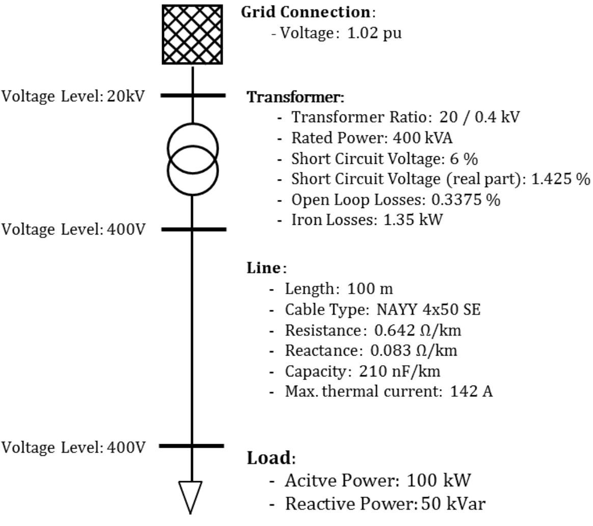
전력 계통 구성 요소 설명
1. Grid Connection (그리드 연결)
• Voltage (전압): 1.02 pu (퍼 유닛)
• 설명: 전력 계통이 외부 그리드와 연결되는 지점을 의미합니다. 퍼 유닛 시스템에서 1.02 pu는 기준 전압 대비 1.02배임을 나타냅니다.
2. Voltage Level (전압 수준)
• 20kV (킬로볼트): 상위 전압 수준을 나타냅니다.
• 400V (볼트): 하위 전압 수준을 나타냅니다.
3. Transformer (변압기)
• Transformer Ratio (변압기 비율): 20 / 0.4 kV
• Rated Power (정격 전력): 400 kVA (킬로볼트암페어)
• Short Circuit Voltage (단락 전압): 6%
• Short Circuit Voltage (real part) (단락 전압 (실제 부분)): 1.425%
• Open Loop Losses (무부하 손실): 0.3375%
• Iron Losses (철손): 1.35 kW (킬로와트)
• 설명: 변압기는 전력 계통 내에서 전압 수준을 변환하는 장치입니다. 주어진 사양은 변압기의 성능과 효율을 나타냅니다.
4. Line (선로)
• Length (길이): 100 m (미터)
• Cable Type (케이블 유형): NAYY 4x50 SE
• Resistance (저항): 0.642 Ω/km (오옴/킬로미터)
• Reactance (리액턴스): 0.083 Ω/km
• Capacity (용량): 210 nF/km (나노패럿/킬로미터)
• Max. thermal current (최대 열 전류): 142 A (암페어)
• 설명: 선로는 전력 계통 내에서 전기를 전달하는 역할을 합니다. 주어진 사양은 선로의 전기적 특성을 나타냅니다.
5. Load (부하)
• Active Power (유효 전력): 100 kW (킬로와트)
• Reactive Power (무효 전력): 50 kVar (킬로바르)
• 설명: 부하는 전력 계통에서 소비되는 전력을 의미합니다. 유효 전력은 실제로 일을 하는 전력을, 무효 전력은 전력 계통 내에서 에너지가 교환되는 전력을 의미합니다.
Python Code
import pandapower as pp
import pandas as pd
#create empty net
net = pp.create_empty_network()
#create buses
b1 = pp.create_bus(net, vn_kv=20., name="Bus 1")
b2 = pp.create_bus(net, vn_kv=0.4, name="Bus 2")
b3 = pp.create_bus(net, vn_kv=0.4, name="Bus 3")
#create bus elements
pp.create_ext_grid(net, bus=b1, vm_pu=1.02, name="Grid Connection")
pp.create_load(net, bus=b3, p_mw=0.1, q_mvar=0.05, name="Load")
#create branch elements
tid = pp.create_transformer(net, hv_bus=b1, lv_bus=b2, std_type="0.4 MVA 20/0.4 kV", name="Trafo")
pp.create_line(net, from_bus=b2, to_bus=b3, length_km=0.1, name="Line",std_type="NAYY 4x50 SE")
pp.runpp(net)
# print results
print("Bus Results:\n", net.res_bus)
print("\nLine Results:\n", net.res_line)
print("\nTransformer Results:\n", net.res_trafo)
print("\nLoad Results:\n", net.res_load)
Result Analysis
### Bus Results
```plaintext
vm_pu va_degree p_mw q_mvar
0 1.020000 0.000000 -0.107265 -0.052675
1 1.008843 -150.760126 0.000000 0.000000
2 0.964431 -149.884141 0.100000 0.050000
```
- **Bus 0 (Grid Connection)**
- `vm_pu`: 1.02 pu - The voltage magnitude is 1.02 times the base voltage.
- `va_degree`: 0.0 degrees - The voltage angle is 0 degrees (reference bus).
- `p_mw`: -0.107265 MW - The active power supplied by the grid.
- `q_mvar`: -0.052675 MVAR - The reactive power supplied by the grid.
- **Bus 1 (Low Voltage Side of Transformer)**
- `vm_pu`: 1.008843 pu - The voltage magnitude is slightly above the base voltage.
- `va_degree`: -150.760126 degrees - The voltage angle is quite large, indicating phase shift.
- `p_mw`: 0.0 MW - No active power injection at this bus.
- `q_mvar`: 0.0 MVAR - No reactive power injection at this bus.
- **Bus 2 (Load Bus)**
- `vm_pu`: 0.964431 pu - The voltage magnitude is slightly below the base voltage.
- `va_degree`: -149.884141 degrees - The voltage angle is also large.
- `p_mw`: 0.1 MW - The active power consumed by the load.
- `q_mvar`: 0.05 MVAR - The reactive power consumed by the load.
### Line Results
```plaintext
p_from_mw q_from_mvar p_to_mw q_to_mvar pl_mw ql_mvar i_from_ka \
0 0.105392 0.050696 -0.1 -0.05 0.005392 0.000696 0.167325
i_to_ka i_ka vm_from_pu va_from_degree vm_to_pu va_to_degree \
0 0.167326 0.167326 1.008843 -150.760126 0.964431 -149.884141
loading_percent
0 117.835208
```
- **Line (Bus 1 to Bus 2)**
- `p_from_mw`: 0.105392 MW - Active power flowing from Bus 1 to Bus 2.
- `q_from_mvar`: 0.050696 MVAR - Reactive power flowing from Bus 1 to Bus 2.
- `p_to_mw`: -0.1 MW - Active power received at Bus 2 (load side).
- `q_to_mvar`: -0.05 MVAR - Reactive power received at Bus 2 (load side).
- `pl_mw`: 0.005392 MW - Active power loss in the line.
- `ql_mvar`: 0.000696 MVAR - Reactive power loss in the line.
- `i_from_ka` and `i_to_ka`: ~0.167 kA - Current flowing through the line.
- `vm_from_pu`: 1.008843 pu - Voltage magnitude at the sending end (Bus 1).
- `va_from_degree`: -150.760126 degrees - Voltage angle at the sending end.
- `vm_to_pu`: 0.964431 pu - Voltage magnitude at the receiving end (Bus 2).
- `va_to_degree`: -149.884141 degrees - Voltage angle at the receiving end.
- `loading_percent`: 117.835208% - The line is overloaded, operating above its thermal limit.
### Transformer Results
```plaintext
p_hv_mw q_hv_mvar p_lv_mw q_lv_mvar pl_mw ql_mvar i_hv_ka \
0 0.107265 0.052675 -0.105392 -0.050696 0.001873 0.001979 0.003382
i_lv_ka vm_hv_pu va_hv_degree vm_lv_pu va_lv_degree loading_percent
0 0.167325 1.02 0.0 1.008843 -150.760126 29.289513
```
- **Transformer (between Bus 0 and Bus 1)**
- `p_hv_mw`: 0.107265 MW - Active power on the high voltage side.
- `q_hv_mvar`: 0.052675 MVAR - Reactive power on the high voltage side.
- `p_lv_mw`: -0.105392 MW - Active power on the low voltage side.
- `q_lv_mvar`: -0.050696 MVAR - Reactive power on the low voltage side.
- `pl_mw`: 0.001873 MW - Active power loss in the transformer.
- `ql_mvar`: 0.001979 MVAR - Reactive power loss in the transformer.
- `i_hv_ka`: 0.003382 kA - Current on the high voltage side.
- `i_lv_ka`: 0.167325 kA - Current on the low voltage side.
- `vm_hv_pu`: 1.02 pu - Voltage magnitude on the high voltage side.
- `va_hv_degree`: 0.0 degrees - Voltage angle on the high voltage side.
- `vm_lv_pu`: 1.008843 pu - Voltage magnitude on the low voltage side.
- `va_lv_degree`: -150.760126 degrees - Voltage angle on the low voltage side.
- `loading_percent`: 29.289513% - Transformer loading is within safe limits.
### Load Results
```plaintext
p_mw q_mvar
0 0.1 0.05
```
- **Load (connected to Bus 2)**
- `p_mw`: 0.1 MW - Active power consumed by the load.
- `q_mvar`: 0.05 MVAR - Reactive power consumed by the load.
### Analysis:
1. **Bus Voltages and Angles:**
- The voltage at Bus 2 is slightly lower than the nominal voltage (0.964431 pu), which is expected due to the load.
- The voltage angles are significant, indicating phase shifts across the network.
2. **Line Loading:**
- The line between Bus 1 and Bus 2 is heavily loaded (117.835208%), exceeding its thermal limit. This indicates a potential issue that needs to be addressed to prevent overheating and damage.
3. **Transformer Loading:**
- The transformer is operating at a safe loading level (29.289513%), indicating it has sufficient capacity to handle the current load.
4. **Power Losses:**
- There are small power losses in both the line and the transformer, which is typical in any power system.
5. **Load Consumption:**
- The load is consuming the expected amount of active (0.1 MW) and reactive power (0.05 MVAR).
### Recommendations:
- **Line Capacity:** Consider upgrading the line to handle higher currents or redistribute the load to prevent overloading.
- **Voltage Regulation:** Monitor and potentially adjust the transformer tap settings or use reactive power compensation to maintain voltage levels within acceptable limits.
These results and analyses provide insights into the performance and potential issues within your power system.
PandaPower Library를 이용한 3 Bus System을 분석해보았습니다. 위의 내용이 도움이 되셨길 바라며, 이만 포스팅을 마칩니다.
'003. 에너지(Power & Energy) Note' 카테고리의 다른 글
| [에너지] 국가별 CO2 배출 가격: 탄소 배출에 대한 최신 동향 (1) | 2024.07.28 |
|---|---|
| [전력] IEC 61850을 활용한 디지털 변전소 자동화 시스템 개요 및 구성 (2) | 2024.07.05 |
| [산업단지] 제조업 Thermal/Electric Load에 대한 분석 (1) | 2024.05.28 |
| [Net-Zero] Grid-connected vs Isolated 형태의 Microgrid 비교/분석 (0) | 2024.05.28 |
| [Daily Load Profile] kWh vs kw의 의미 분석 (0) | 2024.05.28 |